

Interpreting Circuit Breaker Test Results: A Professional’s Guide to Asset Health
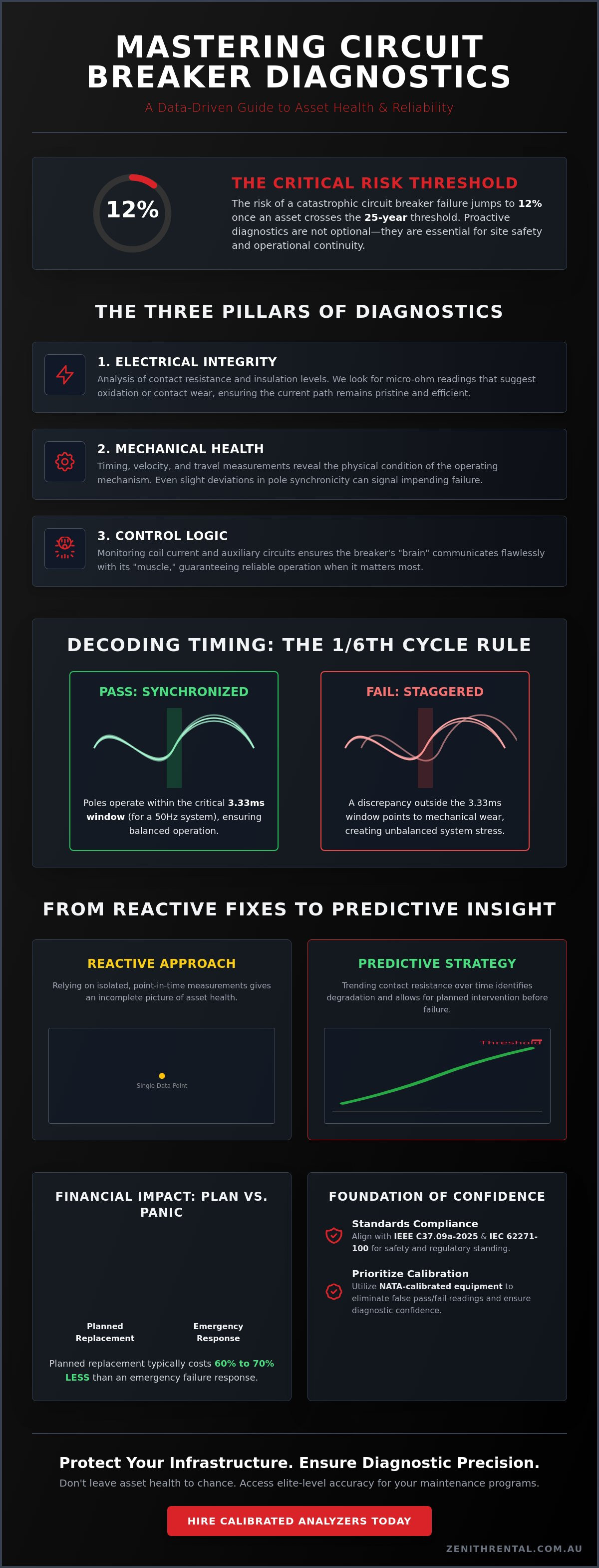
Did you know that the risk of a catastrophic circuit breaker failure jumps to 12% once an asset crosses the 25-year threshold? For the discerning professional, managing these aging assets requires more than just routine checks; it demands a sophisticated understanding of how to read the subtle warning signs hidden within your data. You likely feel the weight of responsibility when faced with ambiguous readings, especially when the pressure to maintain peak operational reliability conflicts with the need for absolute site safety. Mastering the nuances of interpreting circuit breaker test results is the hallmark of a premier asset management strategy, ensuring your facility remains both compliant and resilient.
We'll provide the clear pass/fail criteria you need to eliminate uncertainty and build a data-driven case for your maintenance investments. By aligning your practices with the latest IEEE C37.09a-2025 standards and embracing condition-based maintenance, you can transform technical data into a strategic roadmap for longevity. This article explores the transition from simple timing tests to analyzing complex asset signatures, giving you the confidence to protect your infrastructure and your professional reputation. Let's examine how refined diagnostics turn potential liabilities into high-performing assets.
Key Takeaways
- Define the unique health signature of your assets by contextualizing raw data with age, temperature, and historical performance benchmarks.
- Identify critical mechanical risks by analyzing pole synchronicity and ensuring timing remains within the vital one sixth of a cycle threshold.
- Shift from reactive fixes to predictive maintenance by trending contact resistance over time rather than relying on isolated, point in time measurements.
- Elevate your site's safety and regulatory standing by aligning your process for interpreting circuit breaker test results with international IEC 62271-100 standards.
- Ensure absolute diagnostic confidence by prioritizing the calibration of your testing fleet before categorizing assets into marginal or critical failure states.
The Fundamentals of Diagnostic Interpretation for High-Voltage Assets
A circuit breaker is more than a mechanical switch; it's a sophisticated guardian of your infrastructure. To truly understand its condition, you must define its "Health Signature." This unique profile emerges through multi-parameter testing that looks beyond simple binary outcomes. When interpreting circuit breaker test results, a single number rarely tells the full story. You must view raw data through a lens of specific context: the ambient temperature during the test, the asset's age, and its historical performance benchmarks. This holistic approach, aligned with the latest IEEE C37.09a-2025 standards, ensures that you aren't just reacting to numbers, but managing the heartbeat of your facility with absolute precision.
Precision instrumentation is the cornerstone of this process. Without it, you risk "false failure" readings that trigger unnecessary downtime or, worse, "false pass" results that leave your site vulnerable. High-end diagnostic interpretation relies on the integrity of the data source. Utilizing impeccably maintained test sets, often secured through professional Circuit Breaker Analyzer hire, is a non-negotiable standard for the discerning professional who values reliability over mere utility.
Why Interpretation Outweighs Execution
The industry is moving away from reactive maintenance toward a model of predictive asset health monitoring. This shift requires a refined ability to analyze marginal results. A misinterpreted reading can lead to significant financial loss, either through premature replacement or unexpected failure. Research indicates that planned replacement of a circuit breaker typically costs 60% to 70% less than an emergency response to a failure. To ensure your baseline data is beyond reproach, utilizing NATA-calibrated equipment is essential. It provides the elite-level accuracy required to justify maintenance budgets and secure asset longevity with total confidence.
The Three Pillars of Breaker Diagnostics
A comprehensive diagnostic strategy rests on three distinct yet interconnected pillars that define the asset's operational status:
- Electrical Integrity: This involves analyzing contact resistance and insulation levels. We look for micro-ohm readings that suggest oxidation or contact wear, ensuring the current path remains pristine and efficient.
- Mechanical Health: Timing, velocity, and travel measurements reveal the physical condition of the operating mechanism. Even a slight deviation in pole synchronicity can signal an impending mechanical failure before it manifests as a trip.
- Control Logic: Monitoring coil current and auxiliary circuit performance ensures the "brain" of the breaker communicates seamlessly with the "muscle."
By focusing on these pillars, you move from basic maintenance to a standard of excellence that mirrors the high performance of the assets you protect. This disciplined approach minimizes friction and provides a clear, logical path toward peak operational reliability.
Analyzing Contact Timing and Motion Signatures
Timing is the pulse of a circuit breaker's mechanical health. When you're interpreting circuit breaker test results, the "Open" and "Close" times provide the first glimpse into the asset's internal condition. These results shouldn't just exist in a vacuum; you must weigh them against the manufacturer’s original specifications. A delay of even a few milliseconds can indicate a lack of lubrication or a weakened trip spring. Speed is the essence of protection. If the breaker operates too slowly, the duration of the arc increases, leading to premature contact erosion and potential failure of the quenching medium.
The 1/6th of a cycle threshold is the gold standard for pole synchronicity. In a 50Hz system, this represents a window of approximately 3.33 milliseconds. When poles operate outside this window, you face "staggered" results. This discrepancy often points to mechanical wear in the linkages or misalignment in the drive rod, creating unbalanced stresses on the three-phase system. Detecting these millisecond variances early is what separates an elite asset manager from a reactive one.
Deciphering the Travel Curve
Deciphering the travel curve requires an eye for detail. You want to see a smooth acceleration followed by controlled damping. If the "over-travel" or "rebound" phases show excessive oscillation, the dashpot or mechanical buffers are likely failing. This affects the "contact wipe," which is the distance the contacts remain in touch after the initial engagement. Proper wipe is essential for maintaining low resistance and ensuring arc quenching efficiency. To capture this level of detail, professional circuit breaker analyzer hire provides the high-resolution motion data necessary for a truly sophisticated analysis.
Synchronicity and Phase Discrepancy
Non-simultaneous pole operation introduces transient voltages that can destabilize your network. Over time, mechanical linkages succumb to friction, causing phase discrepancies that compromise safety. According to IEC 62271-100, the maximum pole discrepancy for a three-phase circuit breaker must be strictly maintained to prevent harmful system transients. Identifying contact bounce is equally vital, as these rapid, unintended openings cause unnecessary wear and can signal a loss of contact pressure. For those seeking to maintain the highest possible standard of service, choosing premium electrical test equipment ensures your site stays within these elite performance brackets.
Contact Resistance and Static/Dynamic Analysis
Static resistance testing offers a vital snapshot of contact health, yet its true value emerges through longitudinal analysis. When interpreting circuit breaker test results, a single micro-ohm reading might fall within acceptable limits while masking a dangerous upward trend. Professionals look for consistency across all three phases. A variance of more than 20% between poles often signals a localized issue, such as loose bolting or contact misalignment. By trending these micro-ohm values over several service cycles, you can predict when oxidation will compromise the asset's thermal stability long before a hot spot develops.
Dynamic Resistance Measurement (DRM) takes this analysis a step further by recording resistance during the actual opening and closing stroke. This reveals the "signature" of the arcing contacts, which are designed to sacrifice themselves to protect the main current-carrying surfaces. If the DRM curve shows a shortened arcing contact signature, it's a clear indicator that the breaker's ability to quench arcs is diminished. This level of insight allows for a more refined maintenance schedule, focusing resources exactly where they're needed to maintain absolute site safety.
The Micro-Ohm Threshold
Standard limits for contact resistance vary by voltage class and manufacturer, but a deviation from the factory baseline is always cause for scrutiny. Environmental factors in Australia significantly influence these readings. Switchgear in coastal regions must contend with salt-spray, while assets in the north face extreme humidity; both conditions accelerate the oxidation of silver-plated contacts. To ensure your readings are beyond reproach, selecting the right micro milliohm meter hire is essential. High-current injection, typically 100A or greater, is required to "burn through" minor surface films and reveal the true metal-to-metal resistance of the contacts.
Dynamic Resistance Signatures
Interpreting the DRM curve allows you to assess arcing contact length without a costly internal inspection. A healthy signature shows a clear, sustained period of low resistance as the arcing contacts engage, followed by the transition to the main contacts. Spikes or "noise" in this curve often correlate with mechanical alignment issues or weak contact springs. This data provides a sophisticated way to determine the "remaining life" of your contacts. It transforms raw resistance profiling into a strategic tool for asset longevity, ensuring your high-value infrastructure remains at the peak of its industry standard.
Standards, Compliance, and Regulatory Benchmarks
Excellence in high-voltage asset management is defined by more than just technical proficiency; it requires a disciplined adherence to the highest regulatory benchmarks. When interpreting circuit breaker test results, the distinction between a simple "pass" and a legally defensible "pass" lies in your alignment with established frameworks. While IEC 62271-100 serves as the global cornerstone for defining international testing protocols for high-voltage switchgear, local requirements often demand a more bespoke approach. Navigating the gap between manufacturer specifications and broader industry standards is where true professional authority is demonstrated. Manufacturer specs provide the baseline for a new asset, but industry standards like AS/NZS 3000 ensure that the asset continues to perform safely within the unique constraints of your specific network.
Documentation is the final, vital component of this process. For NATA-compliant site audits, raw data is insufficient. You must provide a clear, logical narrative that explains how the results were obtained, the environmental conditions at the time, and the calibration status of the instruments used. This level of detail transforms a routine report into a prestigious asset health record that stands up to the most rigorous scrutiny from insurers and regulators alike.
Australian Regulatory Context
High-voltage asset owners in Australia carry significant safety obligations. Regular, documented testing is a primary mechanism for mitigating liability under occupational health and safety laws. In the event of an incident, the ability to produce NATA-traceable data is your strongest defense. This requires more than just skilled personnel; it demands the use of high-end tools. Utilizing professional test equipment hire Australia ensures that every analyzer and micro-ohm meter in your fleet carries a current, valid calibration certificate, providing the absolute reliability your stakeholders expect.
IEC vs. AS/NZS: Key Differences
While international standards focus on broad performance categories, local Australian utility requirements are often more stringent regarding timing tolerances and phase discrepancy. IEC 62271-100 provides the framework for timing in cycles, but local network service providers may specify millisecond-perfect windows to protect sensitive regional infrastructure. NATA-traceable results are the gold standard for Australian compliance, providing an unshakeable audit trail for insurance and safety regulators. For professionals who refuse to compromise on quality, choosing premium electrical testing equipment ensures your compliance strategy is as refined as the assets you manage.
Strategic Decision Making: From Data to Action
The transition from raw data to strategic action defines the true value of a professional asset manager. When interpreting circuit breaker test results, categorizing findings into Acceptable, Marginal, and Critical tiers is essential for maintaining site safety. Acceptable results validate your existing maintenance cycle, while Critical findings demand an immediate pause to prevent catastrophic failure. Marginal results, however, present the greatest opportunity for professional discernment. They signal that an asset is drifting from its baseline, allowing you to intervene before safety is compromised or unplanned downtime becomes a necessity.
Before committing to major repairs, you must account for the "Calibration Variable." Misleading data often points to an aging or unverified test fleet rather than the breaker itself. If your instruments lack current NATA verification, your interpretation rests on a shaky foundation. Ensuring your diagnostic tools are as reliable as the assets they test is the first step in any sophisticated asset management plan. This eliminates the risk of false failures and provides the data-driven justification needed for significant capital expenditure.
Addressing Marginal Results
When results fall into the marginal bracket, eliminating external errors is your first task. High lead resistance or poor terminal connections can easily mimic contact oxidation. A meticulous re-test with precision-calibrated instruments often clarifies these ambiguities. In complex protection schemes, utilizing three phase relay tester hire allows you to verify the entire logic chain. This ensures the trip signal and the breaker's response are synchronized with the millisecond precision required by modern standards, providing a holistic view of the protection system's health.
The Elite Rental Model
Maintaining a prestigious testing standard doesn't require a prohibitive capital burden. The elite rental model allows you to bypass the "Obsolescence Risk" by accessing the latest Megger and Fluke technology on demand. By choosing Zenith Rental, you gain immediate access to a fleet that is pre-calibrated and project-ready for Australian industrial environments. This strategic approach ensures 100% uptime and reduces the total cost of ownership while elevating your testing standards to a level of absolute reliability. You don't just hire equipment; you secure a partnership that values the quality of your time and the longevity of your high-value assets.
Securing the Future of Your High-Voltage Infrastructure
Mastering the nuances of interpreting circuit breaker test results is the hallmark of a premier asset management strategy. Throughout this guide, we have explored how mechanical synchronicity and dynamic resistance profiles converge to form a comprehensive health signature for your switchgear. Aligning these technical findings with Australian regulatory benchmarks doesn't just ensure compliance; it transforms your maintenance routine into a sophisticated tool for predicting failure before it occurs. By moving beyond simple pass/fail metrics toward data-driven trends, you secure the longevity of your high-value assets and the ongoing safety of your facility.
Achieving this level of diagnostic excellence requires a partner who understands the finer details of high-voltage testing. Explore our elite range of calibrated Circuit Breaker Analyzers for hire and experience the absolute reliability of world-leading brands like Megger and Fluke. Zenith Rental provides NATA-traceable calibration on every instrument, supported by seamless nationwide delivery across Australia to ensure your project remains on schedule. Entrust your diagnostic requirements to a partner that prioritizes your success and the peak performance of your infrastructure.
Frequently Asked Questions
What is a "normal" contact resistance for a high-voltage circuit breaker?
A normal contact resistance reading typically falls within the range of 10 to 100 micro-ohms, depending on the voltage class and manufacturer specifications. For new high-voltage breakers, readings are often significantly lower, sometimes staying below 50 micro-ohms. The key is to compare the results against the factory test report. Any deviation greater than 20% between phases or a departure from the historical baseline warrants a detailed investigation into potential contact oxidation or misalignment.
How does temperature affect the interpretation of timing test results?
Ambient temperature influences the viscosity of lubricants within the operating mechanism, which can alter timing results. In colder environments, thickened grease may slow the "Open" or "Close" operations by several milliseconds. When interpreting circuit breaker test results, it's essential to record the temperature at the time of testing. This allows you to normalize the data and ensure that a slight timing delay is a thermal variance rather than a mechanical failure.
What is the difference between static and dynamic resistance testing?
Static resistance testing measures the contact integrity while the breaker is fully closed, whereas dynamic resistance testing (DRM) records resistance throughout the entire opening or closing stroke. While static tests identify surface oxidation and loose connections, DRM provides a sophisticated view of the arcing contacts. This distinction is vital for assessing the wear of internal components that are not visible during a standard closed-state measurement, offering a deeper insight into the asset's remaining life.
Why is coil current measurement included in circuit breaker analysis?
Coil current measurement is included to diagnose the health of the trip and close coils and the mechanical state of the latching system. The current "signature" reveals the coil's electrical integrity and the mechanical force required to release the mechanism. Anomalies in the peak current or the duration of the curve often signal impending coil failure or excessive friction in the auxiliary linkages, allowing for proactive replacement before a failure to trip occurs.
How often should circuit breaker testing be performed in Australian industrial environments?
Australian industrial environments typically follow a testing cycle of every three to six years, though highly critical assets or those in harsh coastal conditions may require more frequent attention. AS/NZS 3000 and utility-specific guidelines emphasize condition-based monitoring over rigid calendars. If an asset experiences a high number of operations or a significant fault-clearing event, an immediate diagnostic check is recommended to ensure the continued safety and reliability of the local network.
What should I do if my test results are slightly outside the manufacturer’s specifications?
If results deviate slightly from specifications, your first step should be to verify the test setup and lead connections to eliminate measurement error. Once confirmed, interpreting circuit breaker test results that fall into this "marginal" category requires a sophisticated cost-benefit analysis. This status doesn't always necessitate immediate replacement but does require increased monitoring frequency. A professional assessment will determine if the variance is a stable aging characteristic or a trend toward a critical failure state.
Can I use a standard multimeter for contact resistance testing?
No, a standard multimeter is insufficient for contact resistance testing because it lacks the high-current injection required to overcome surface films. Accurate micro-ohm readings require a dedicated micro-milliohm meter capable of injecting at least 100A. This high current "burns through" minor oxidation to reveal the true metal-to-metal resistance, providing the elite-level accuracy necessary for high-voltage diagnostics and regulatory compliance.