


Insulation Testing Best Practices: 2026 Engineering Guide
Relying on a single-point spot check to verify dielectric health is one of the costliest gambles an engineering team can make. While a standard reading might show an acceptable megohm value on paper, it often masks localized voids, thermal degradation, or moisture ingress lurking within high-value apparatus. Establishing rigorous best practices for insulation testing transforms routine maintenance into true predictive intelligence, protecting personnel and mission-critical systems against sudden flashovers.
You already know the frustration of chasing erratic readings skewed by ambient humidity, or the anxiety of proof-testing legacy windings without triggering an arc flash. This 2026 engineering guide delivers the exact framework needed to master precision insulation resistance diagnostics, navigate AS/NZS 3000 compliance, and select the right instrumentation to safeguard critical infrastructure. We'll explore how to interpret Polarization Index (PI) and Dielectric Absorption Ratio (DAR) curves, establish rock-solid standard operating procedures, and eliminate asset uncertainty with unyielding precision.
Key Takeaways
- Differentiate between capacitive charging, dielectric absorption, and leakage currents to identify genuine insulation degradation before catastrophic breakdown occurs.
- Adopt the industry's best practices for insulation testing by replacing unreliable spot checks with multi-curve Polarization Index (PI) and Dielectric Absorption Ratio (DAR) diagnostics.
- Select correct DC test voltages matched to asset ratings and normalize field data against ambient temperatures to satisfy AS/NZS 3000 compliance benchmarks.
- Protect testing teams during high-voltage procedures with strict lock-out tag-out protocols and mandatory controlled discharge of stored capacitive energy.
- Eliminate depreciating capital costs and guarantee audit-ready precision by sourcing elite, pre-calibrated diagnostic instruments on demand.
Fundamentals of Electrical Insulation Resistance: What Every Engineer Must Measure
Insulation resistance testing is a non-destructive quantitative safety audit designed to evaluate the dielectric integrity of critical industrial electrical systems before energization. High-voltage cables, power transformers, switchgear, and rotating machines depend entirely on pristine insulating media to contain electrical stress. Over operational lifecycles, insulation naturally deteriorates under constant thermal stress, operational vibration, airborne chemical contaminants, and moisture ingress. Implementing rigorous best practices for insulation testing allows engineering teams to identify internal micro-fissures and moisture penetration long before catastrophic dielectric breakdown takes an asset offline.
The Anatomy of Total Test Current
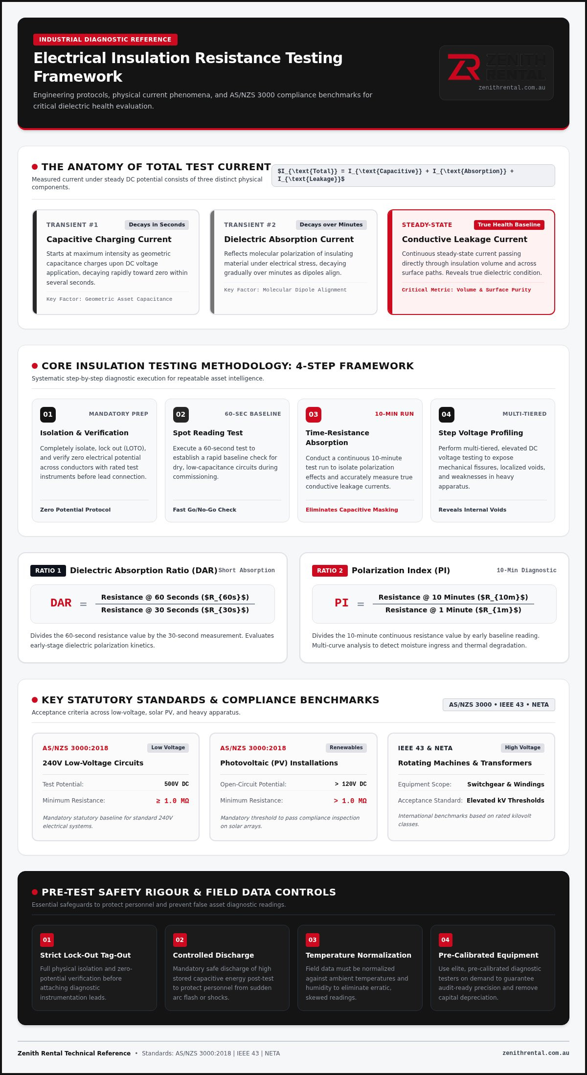
When applying a steady direct current potential across an insulating barrier, the measured current is not a single static value. Instead, it reflects the sum of three distinct physical phenomena. Grasping these interactions is central to mastering the Fundamentals of the Megohmmeter and modern high-voltage diagnostics:
- Capacitive Charging Current: Starts at maximum intensity as the geometric capacitance of the asset charges, decaying rapidly toward zero within several seconds of voltage application.
- Dielectric Absorption Current: Represents the molecular polarization of the insulating material under electrical stress, decaying gradually over minutes as dipoles align.
- Conductive Leakage Current: Represents the continuous, steady-state current passing directly through the insulation volume and across contaminated surface paths. This component reveals the true baseline health of the dielectric material.
Key Standards Governing Australian Industrial Testing
Asset health evaluations must strictly align with statutory guidelines. Within Australia, AS/NZS 3000:2018 sets clear baselines for low-voltage systems, establishing a minimum acceptable insulation resistance of 1 MΩ for circuits operating at 240V when evaluated at a test potential of 500V DC. Photovoltaic installations with open-circuit potentials above 120V DC must also maintain resistance levels greater than 1 MΩ to pass inspection.
For high-voltage rotating machinery, transformers, and distribution gear, site engineers reference international benchmarks such as IEEE 43 and NETA specifications. These standards define elevated acceptance thresholds based on rated kilovolt classes, ensuring that maintenance teams execute repeatable, audit-ready evaluations across legacy and modern equipment alike.
Core Insulation Testing Methodologies: Step-by-Step Diagnostic Frameworks
Systematic execution separates conclusive diagnostic intelligence from guesswork. Establishing standard operating procedures based on industry-recognized best practices for insulation testing protects plant assets and field personnel during high-voltage diagnostic shutdowns:
- Step 1: Isolation and Verification: Completely isolate, lock out, and verify zero electrical potential across conductors with rated test instruments before attaching diagnostic leads.
- Step 2: Spot Reading Test: Execute a 60-second test to establish a quick baseline check for dry, low-capacitance circuits.
- Step 3: Time-Resistance Absorption Test: Conduct a continuous 10-minute run to isolate polarization effects and measure leakage currents accurately.
- Step 4: Step Voltage Profiling: Perform multi-tiered, elevated DC voltage tests to expose mechanical fissures and localized voids within heavy electrical apparatus.
Short-Time Spot Reading vs Time-Resistance Testing
Spot reading tests offer a rapid go/no-go evaluation during initial commissioning. For large rotating machinery or lengthy distribution cables, single readings fall short because capacitive charging currents mask real leakage values. Time-resistance testing resolves this limitation by evaluating how dielectric resistance evolves over time.
Engineers calculate two primary metrics from these tests: the Dielectric Absorption Ratio (DAR), which divides the 60-second resistance value by the 30-second measurement, and the Polarization Index (PI), which divides the 10-minute value by the 1-minute value. According to IEEE 43 guidelines, healthy modern insulation typically exhibits a PI above 2.0. A PI value below 1.5 indicates excessive moisture, dirt accumulation, or advanced thermal degradation that requires immediate intervention.
Advanced Step Voltage and Ramp Diagnostics
Step voltage testing subjects equipment to incremental voltage levels, usually applied in five equal stages over 60-second intervals up to the target potential. In sound dielectric media, measured resistance remains relatively steady across all tiers. If resistance drops markedly as the potential increases, the test reveals pinholes, physical cracking, and carbonized tracking paths that lower potentials cannot expose.
Ramp testing applies a continuous, linear voltage rise while sampling micro-amp leakage rates. A non-linear spike in leakage current warns engineers of imminent dielectric breakdown, allowing them to stop the test before causing permanent damage to the winding or cable insulation. Documenting these nuanced curves pairs naturally with tailored test equipment hire Australia strategies, giving your team immediate access to sophisticated diagnostic analyzers without the burden of idle capital storage.
Diagnostic Test Voltage Selection and Environmental Normalization
Precision diagnostics require matching the applied potential to asset insulation ratings. Applying insufficient test voltage leaves deep insulation weaknesses undetectable, while excessive electrical potential risks puncture through aged dielectric barriers. Aligning your voltage profile with operational specifications represents one of the foundational best practices for insulation testing, ensuring tests remain non-destructive while uncovering latent faults.
DC Test Voltage Selection Framework
Test voltages must reflect the rated operational capacity and internal construction of the apparatus under test:
- 250V DC: Reserved for low-voltage telecommunication circuits, instrumentation loops, and sensitive solid-state electronic controls that suffer dielectric breakdown under higher field stresses.
- 500V DC: Applied to standard 230V/400V low-voltage installations, sub-mains, and distribution panels compliant with Australian wiring standards.
- 1000V DC: Suited for 415V to 690V industrial motors, drives, and heavy power feeders requiring rigorous proof screening.
- 2.5kV to 10kV DC: Mandatory for medium-to-high voltage power distribution assets, including 3.3kV, 6.6kV, and 11kV transformers, large stator windings, and switchgear lineups.
Temperature Normalization and Guard Terminal Application
Raw insulation resistance values taken in the field are meaningless without ambient normalization. Dielectric resistance varies inversely with thermal activity. As a standard engineering benchmark, insulation resistance halves for every 10-degree Celsius rise in temperature. If you record a 100 MΩ reading at 40°C, the true health of the asset cannot be compared directly against historical winter baselines taken at 20°C without applying the appropriate correction coefficient ($R_{20} = R_T \times K_T$). Always normalize your field data to a standard 20°C baseline before plotting condition trends.
Moisture, condensation, and airborne dust also create misleading parallel leakage paths over external insulator bushings. Left unaddressed, surface tracking drags down total measured resistance, leading engineers to mistakenly condemn intact windings. Connecting the third instrument lead, the guard terminal, intercepts this surface current before it passes through the measuring circuit. By routing superficial tracking around the meter, the instrument captures only true volumetric leakage through the internal dielectric mass.
Pre-Test Safety Protocols, Calibration Rigour, and Common Pitfalls
High-voltage diagnostics demand absolute discipline on site. Even the most sophisticated analytical methods fail if physical safety precautions or instrument verification steps are compromised. Flawless test execution rests on two pillars: isolating personnel from lethal residual voltages and ensuring measurement instruments produce defensible, audit-ready data. Observing these pre-test best practices for insulation testing protects testing crews and preserves data integrity across high-value plant operations.
Critical Safety and Capacitive Discharge Protocols
Safety begins with positive physical disconnection. Technicians must enforce strict lock-out tag-out (LOTO) protocols, thoroughly inspecting test leads, silicone insulation, and alligator clamps for micro-fractures before approaching the test specimen. Once isolated, verify zero electrical potential using a proven, calibrated multimeter before attaching high-voltage leads.
De-energizing does not mean an asset is discharged. Long distribution cables, large generators, and power transformers act as substantial capacitors, holding lethal direct-current potentials long after the test concludes. Follow the four-to-one safety rule: maintain a direct, grounded discharge connection for at least four times the duration of the applied test voltage. For high-voltage step and ramp sequences, establish physical exclusion barricades to prevent unauthorized personnel from entering induction zones.
Ensuring Measurement Integrity and Audit Traceability
Diagnostic repeatability relies entirely on instrument accuracy. Out-of-calibration testers drift over time, introducing phantom resistance drops that create false alarms or, worse, overlook genuine dielectric failure. Maintaining pristine calibration records is essential during compliance reporting and statutory asset condition audits.
Leading facility managers avoid measurement uncertainty by referencing the rigorous precision benchmarks outlined in the legacy of Fluke. Every field log sheet must systematically capture ambient dry-bulb temperature, relative humidity, equipment operating temperatures, and instrument serial numbers. If your current testing tools lack current calibration credentials or struggle to maintain voltage stability under load, hire certified electrical testing equipment from an accredited instrumentation partner to secure verified, audit-proof diagnostics across every industrial shutdown.
Executing Advanced Insulation Audits: Securing Premium Equipment On Demand
High-voltage diagnostic programs represent substantial investments in operational integrity, yet hardware procurement hurdles often stall critical timelines. Purchasing high-tier 5kV and 10kV insulation testers outright frequently ties up vital capital in assets that sit idle between annual maintenance turnarounds. Elevating your facility's best practices for insulation testing means adopting an agile procurement model, pairing elite diagnostic capability directly with scheduled shutdown windows.
Capital Expenditure vs Flexible Equipment Hire
Owning high-voltage diagnostic apparatus introduces ongoing hidden overheads. Annual laboratory calibration cycles, battery maintenance, storage overheads, and eventual technological obsolescence steadily inflate the total cost of ownership. These burdens offer poor financial returns when testing occurs only during major turnarounds or scheduled substation overhauls.
Shifting to flexible equipment hire optimizes operational expenditure budgets. Engineering teams bypass lengthy corporate capital approval cycles, securing immediate access to top-tier 10kV diagnostic platforms precisely when project milestones demand them. This agile approach guarantees your engineers always deploy cutting-edge technology without carrying depreciating hardware on the balance sheet.
Selecting the Optimal Hire Partner for Industrial Reliability
Audit integrity depends entirely on the calibration lineage of your diagnostic tools. When statutory safety regulators or insurance underwriters review plant commissioning records, non-traceable test data introduces unacceptable operational risk. A premier instrumentation partner provides certified, audit-ready units backed by comprehensive calibration documentation for total peace of mind on site.
Zenith Rental maintains an extensive national inventory of industry-leading brands, including Megger equipment hire Australia and advanced Fluke diagnostic units. Every instrument arrives pristine, fully verified, and ready for immediate deployment to support mission-critical maintenance schedules. Secure the diagnostic precision your infrastructure deserves and initiate your next campaign with professional test equipment rental built to uphold the highest best practices for insulation testing across the country.
Mastering Dielectric Reliability Across Your Industrial Assets
Modern electrical infrastructure leaves no margin for dielectric ambiguity. Moving beyond elementary spot checks to multi-curve time-resistance profiling, standardizing thermal normalization at 20°C, and observing disciplined four-to-one capacitive discharge protocols ensure lasting equipment protection. Systematically embedding these best practices for insulation testing transforms routine maintenance shutdowns into decisive predictive intelligence, preventing catastrophic arc flash events and unplanned outages.
Achieving this level of precision doesn't require heavy capital outlays on depreciating hardware. Partnering with a dedicated instrumentation specialist gives your facility seamless access to an extensive national inventory of pre-calibrated Megger and Fluke diagnostic testers. Every unit arrives with certified, audit-ready documentation and is backed by specialist engineering support for critical industrial power systems. Secure calibrated insulation resistance testers for your next industrial audit and safeguard your high-value assets with unyielding confidence.
Frequently Asked Questions
What is the minimum acceptable insulation resistance value for electrical systems?
Under AS/NZS 3000:2018, the statutory minimum acceptable insulation resistance for low-voltage circuits operating at 240V is 1 MΩ tested at 500V DC. Photovoltaic arrays exceeding 120V DC also require a minimum 1 MΩ threshold. For medium- and high-voltage rotating machines or switchgear, standards like IEEE 43 specify a base calculation of rated kV plus 1 MΩ, with healthy modern installations typically achieving readings well into hundreds of megohms or gigohms.
How do temperature and ambient humidity affect insulation resistance test readings?
Temperature and moisture exert profound effects on dielectric measurements. Following best practices for insulation testing, engineers normalize field readings to 20°C because insulation resistance roughly halves for every 10°C rise in winding temperature. High relative humidity causes surface condensation on bushings and terminals. This creates conductive leakage paths that falsely depress readings unless you connect the tester's guard terminal to bypass external surface tracking.
Why is a 10-minute Polarization Index test more reliable than a 1-minute spot test?
A 1-minute spot test only measures a snapshot where capacitive charging and absorption currents haven't fully settled. High-capacitance assets like large motors require sustained potential for dielectric molecules to polarize. Calculating the Polarization Index by dividing the 10-minute value by the 1-minute reading provides a true time-resistance ratio independent of baseline temperature. A result above 2.0 confirms dry, resilient insulation, whereas values under 1.5 reveal severe contamination.
What is the difference between an insulation resistance test and a high-potential (Hipot) test?
While both assess dielectric condition, they serve distinct operational objectives. An insulation resistance test measures quantitative resistance in megohms or gigohms using direct current to determine operational health non-destructively. Conversely, a Hipot test applies significantly higher stress, often two times operating voltage plus 1000V in AC or DC, as a pass-fail proof test. Hipot testing verifies physical clearance and dielectric withstand capability under extreme fault or overvoltage conditions.
Can high-voltage insulation testing damage sensitive electronic equipment connected to the circuit?
Yes, applying 500V or 1000V DC test voltages directly into circuits containing sensitive solid-state devices will destroy them. Solid-state relays, variable speed drives, PLC cards, and surge protection devices (SPDs) cannot withstand diagnostic overpotentials. Rigorous best practices for insulation testing require physically disconnecting or bridging electronic components before energizing the test circuit. For dedicated electronic networks or signal lines, restrict testing potentials to a safe 250V DC threshold.
How long must an electrical conductor be discharged after completing an insulation test?
Electrical conductors must remain grounded for at least four times the total duration of voltage application. Long sub-sea feeds, shielded cables, and high-voltage transformer windings store substantial capacitive energy during direct-current testing. Even when the instrument display drops to zero volts, internal dielectric absorption can trigger a lethal voltage rebound. Connecting rated ground discharge leads ensures all stored energy bleeds safely to earth before technicians handle conductors.
Why is certified instrument calibration essential for industrial compliance audits?
Certified calibration guarantees that diagnostic readings remain defensible during statutory inspections, insurer reviews, and asset warranty claims. Over time, internal measurement resistors and voltage output stages drift due to mechanical shock and thermal cycles. Testing with unverified gear introduces compliance liability and risks masking true dielectric deterioration. Sourcing pre-calibrated instrumentation with traceable calibration documentation ensures total measurement accuracy and seamless audit compliance across demanding shutdown schedules.